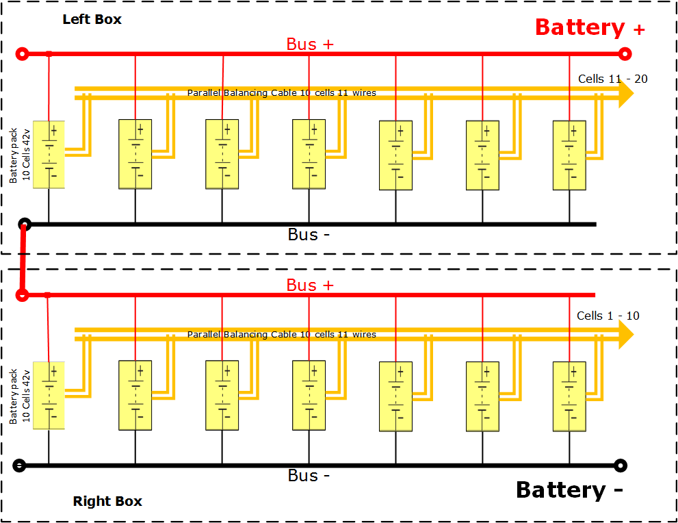
Battery is made of the Lithium Polymer cells. It consists of two battery boxes connected in series.
Each box contains 7 battery packs – each is 10S1P and all packs wired to have 10 battery cells in series and 7 cells in parallel making 10S 7P architecture per box. Total two boxes make 20S7P architecture producing a total nominal 3.7v x 20 = 74v varying from 84v after full charge and down to 64v to the allowable discharge level. 7 parallel packs allow 40 amps of continuous power output at 1C level whence rendering ~3kWh of nominal power.
About burst-in maximum load : as claimed by a manufacturer the battery cells allow 25C discharge level which is typically over stated. The actual maximum discharge current (burst-in load such as a steep climb) allowed in eBirdman propulsion system is no more than 280A which is only 7C from nominal. This provides a significant safety to keep temperature of the battery cool.
Each battery box also houses a BMS board for monitoring battery cells and reporting to the IFC controller the status and voltage of each cell.
IFC monitors the status of the cells showing the following on the display: voltage of all the cells (numerical and graphical) and status of the cell graphically, showing alarm in case
- if any cell reaches the low limit
- if all the battery compound voltage reaches the low limit
- if communication with BMS is lost or a wiring to a cell is lost
Beware though that reaching the low level triggering alarm does not in itself mean that the system is already failing but only a warning of the approaching failure. The margin is built into the system allowing the time for pilot’s decision making.
For ex. the allowed low state of charge of the battery cell is 3.0v yet the system triggers alarm when the cell reaches 3.2v . This situation may be a result of the voltage drop from the heavy load (steep climb on high RPM for ex.) and could be solved by simply decreasing the motor RPM and either continuing at cruise speed or heading for a landing. If the load is reduced the battery cell will bounce back to higher than it’s alarm level. Pilot may observe the actual graph of the battery cell and quickly make a right decision.
Similarly the total battery low voltage triggering alarm still can be running if the load is reduced and battery will bounce back above h alarm level. Even at the same load, if all the cells are showing the same level and temperature sensors show within normal range, battery can be operated down to 60v at which level the manual power down and emergency landing is a must.
All the battery data is getting logged into the log file on IFC MicroSD card every 1 sec and is updated on the display every 0.5 sec.
Below picture shows two battery boxes wiring.

