This got into the Electric Propulsion description only because currently avionics module is implemented inside the In Flight Controller and it functions in tandem with IFC and also uses IFC display screen as visual avionics gadget.
The avionics group includes Airspeed, Absolute Altitude, Relative Altitude and Vario – audio and visual.
All altitude related parameters (Absolute Altitude, Relative Altitude and Vario ) are based on the reading from the Atmospheric Pressure sensor inside the Avionics module mounted in IFC box.
The Airspeed is calculated from the reading of the airspeed sensor inside the Avionics module mounted in IFC box. Pitot tube hoses run through the front of the IFC box.
Airspeed
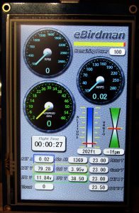
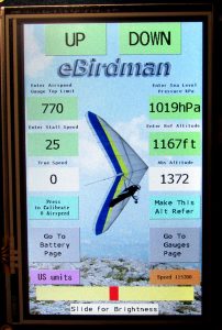
Below are the Gauges display screen showing the Avionics gauges and the Setup screen showing the buttons for the configuration and calibration of avionics.


Airspeed indicator is both dial and a numerical text field on the Gauges screen. Dial’ pointer position is updated every 0.5 sec. in mph.
Currently dial is arranged for the speed range 0 – 60 mph for the duration of the flight tests (subject to change) but the numerical field is not limited.
Calibration of this gauges is done in 1 step : 0 speed calibration in the Setup screen.
To calibrate ‘0’ speed:
- cover the tip of the pitot tube or make sure that there is no air movement during the calibration.
- Press the Press to Calibrate 0 Airspeed button. Done.
In Flight Controller is running this code every time you Power it up or do Reset. If your pitot tube is covered during the Power up or Reset, then your ‘0’ speed setup is done. But the Setup screen button method is needed also after some time (between the flights for example) when the reading of Airspeed starts shifting due to temperature change (currently the airspeed sensor is analog and it’s ‘0’ calibration is drifting significantly as the temperature changes).
The final value of this calibration is recorded to EEPROM and will be restored during the re-powering or after the next Reset. This completes the process of Airspeed calibration.
Top Speed and Stall Speed fields are there to be used for the respective warnings implementation in the future.
Altitude
The Absolute Altitude is displayed on the Gauge screen and also in the Setup screen. Units in feet.
The Absolute Altitude reading is a function of the pre-set value of the Sea Level Pressure (or further SLP ) which is a changing parameter for any given locality. It is provided on the whether related websites in a number of units. eBirdman system uses hPa units to enter this parameter. Subject to the precision of this entered parameter, the Absolute Altitude reading can be precise up to few feet. Changing of SLP is done by pressing Enter Sea Level Pressure button and then following the procedure for changing green buttons described in the Setup Display Page.
Initially, during the first powering up of the system, the default value of 1018 hPa will be recorded in EEPROM but it is unlikely that it will match SLP at your flying location at the time of flying.
Another method to calibrate the Absolute Altitude gauge can be utilized if you know the true altitude of your flying location. The Setup screen where you change the SLP value, shows you the resulting Absolute Altitude number so the user can simply keep changing SLP using UP and DOWN keys until he reaches the known absolute altitude. This method does not need finding out the SLP for a given known location.
The Relative Altitude is displayed visually on the graphic bar and also in the numerical field on the Gauges screen. It is a difference between the Absolute Altitude (shown on the same screen) and a Reference Altitude setup in the Setup screen.
Configuration of Ref Altitude is done by pressing Ref Altitude green button on the Setup screen and then following the procedure for changing green buttons described in the Setup Display Page.
Another alternative method is to press Make This Alt Ref button. You should see immediately your current value for Absolute Altitude as Ref Altitude green button. In other words two fields now show the same number: Ref Altitude and Abs Altitude. Once it is done, the Relative Altitude on the Gauges screen will show ‘0’ (middle bar level position).
Vario
It is also based on the reading from the Atmospheric Pressure sensor. Vario is rendered visually on the Gauge screen as a vertical slider bar and also a numerical field below. Vario produces audible sound through the speaker mounted in IFC box and also earphone jack (later) on the front panel of IFC box.
Sound volume can be adjusted using the dial potentiometer on the front panel or it can be switched off completely by turning the same potentiometer all the way counter-clockwise.
Visual pointer on the Vario vertical bar shows the speed of climb or descent from ‘0’ (center position) to the max scale which is currently +/- 500 ft/min in US standard. Subject to further experimentation in test flights. This visual vario limits are programmed in the code.
