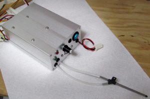
This is the main “brain” of the propulsion system. IFC communicates with other components over digital interfaces, monitors their data and displays the results on IFC Display.
IFC also houses and internally communicates with Avionics module and outputs Avionics data on it’s display.

All the interface cables connecting to the system components run from the back of the IFC box (in the left-to-right order):
- TTY Serial Display cable
- I2C Serial Amperage sensor cable
- (SPI Avionics cable internally connected to Avionics module)
- SPI BMS cable
- RPM 3-wire cable
- 1-wire temperature sensors bus
- 4-wire Thrust sensor cable
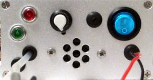
Front plate of the module shown below :
- Green Reset button
- Red Multi-function (Calibration) button
- air pressure tubes connecting to airspeed pitot tube
- Audio control potentiometer to adjust sound volume and also to turn off sound.
- Audio speaker
- Power ON switch with LED
- Power wires

The sequence of connecting IFC module into the system wiring is as follows:
- make sure IFC power switch is OFF, Key switch is OFF and Kill Switch is ON preventing the motor to run
- connect IFC battery pack to the IFC module’ power connector (Power LED should be OFF)
- connect air tubes to the pitot if they are not attached. Observe correct mounting or the airspeed reading will be incorrect – the top tube connects to the direct pitot tube (forward air movement pressure) and bottom tube connects to the angled pitot tube (ambient air pressure)
- connect all the IFC back cables to the respective system components following the marking on the connectors
- After all wiring is checked, turn on IFC Power switch, observe Power LED light ON and the IFC display powered up and shows the Setup screen .
- Check all the IFC display screens for proper operation and for correct battery readings before turning the Key switch and releasing the Kill switch to allow motor to run.
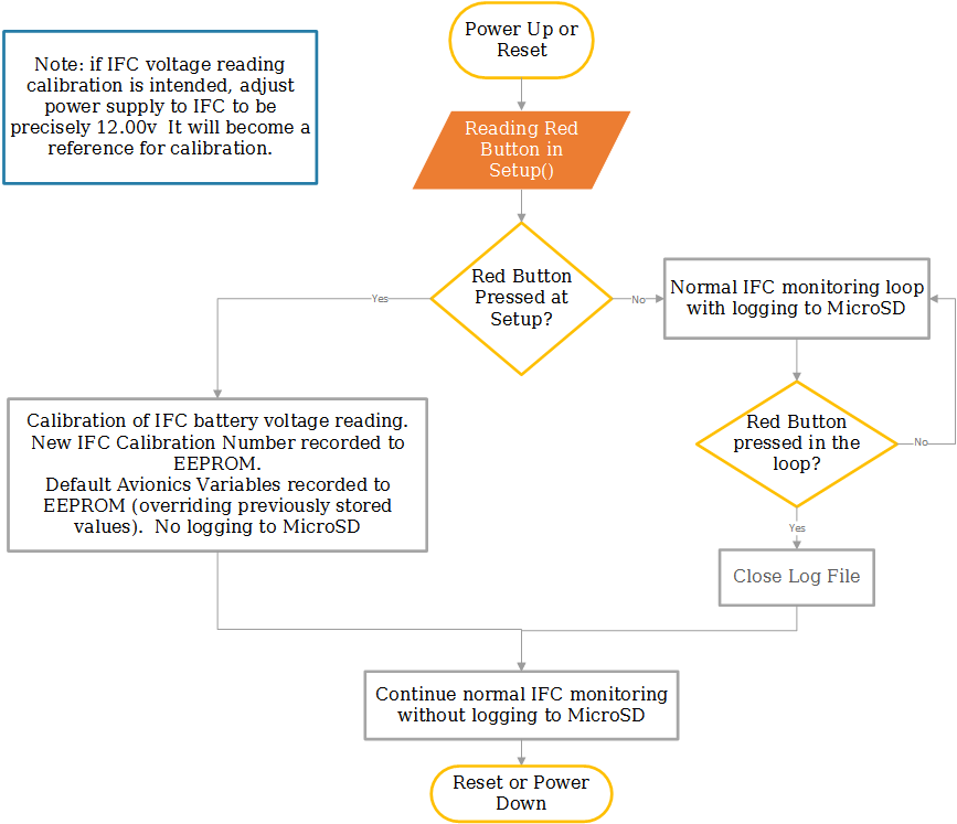
Multi-function Red Button on the front panel changes the mode of IFC operations to the following:
- If Red Button pressed prior and held down during Power up or Reset, then Setup routine will run calibration and initialization of EEPROM with default initial values , then IFC runs normal monitoring loop without logging to MicroSD card.
- If Power Up or Reset started without pressed Red Button, then normal monitoring run with automatic logging of all the data to MicroSD card in a loop until Red Button is pressed while in a loop. If Red Button pressed afterwards, then log file is closed and monitoring continues without logging.
The State Event Diagram showing the modes of IFC operations driven by the input buttons is shown below.

